Key Takeaways & Executive Findings
- •• • CaF2 exhibits a Young's modulus of 110.04 GPa, Poisson's ratio <1/3, and hardness of 5.71 GPa, with elastic anisotropy factors between 0 and 1, confirming soft-brittle behavior that causes brittle fracture during conventional cutting; this necessitates auxiliary strategies to maintain ductile-mode removal for optical surface integrity. • • Fly-cutting achieves a radius error of (0.23±0.04)% and profile error RMS of (208.2±5.76) nm, whereas ultrasonic elliptical vibration cutting (EVC) yields an average profile RMS of 405.56 nm and radius error of 4.56%, with EVC introducing scratches and bottom defects; fly-cutting is thus superior for stable profile accuracy and low roughness in CMLA fabrication. • • Tool geometric errors are directly replicated onto the workpiece, dominating profile error; after correcting the non-circular-arc tool profile, workpiece profile error RMS dropped from 200 nm to 16.8 nm, demonstrating that tool contour accuracy is the primary lever for achieving sub-20 nm form accuracy in microlens arrays. • • Tool wear is concentrated at the tip due to long cutting strokes, while middle sections wear less, driven by repeated edge cutting and localized thermo-mechanical friction; this wear progression shifts profile accuracy from a geometry-dominated to a wear-dominated regime, requiring tool life management for sustained precision.
China Advanced Materials & Deep-Tech Radar
Get verified English translations, SEM micrographs & open-access PDF alerts from China's leading state key laboratories delivered to your inbox every Monday at 08:00 EST.
Abstract
Fabrication of high-precision cylindrical microlens arrays (CMLA) on single-crystal calcium fluoride (CaF2) substrates is critical for advanced lithographic illumination systems. However, the intrinsic soft-brittle characteristics and weak elastic anisotropy of CaF2 often induce brittle fracture and surface damage during ultra-precision machining, limiting achievable form accuracy and surface quality. This study systematically investigates the coupling relationship between profile accuracy and surface integrity in diamond machining of CaF2 CMLA, emphasizing material properties, auxiliary cutting strategies, tool geometric accuracy, and tool wear evolution. First, fundamental mechanical properties of CaF2 are analyzed from elastic constants. Calculations show a Young's modulus of 110.04 GPa, Poisson's ratio below 1/3, and hardness of 5.71 GPa, confirming typical soft-brittle nature. The elastic anisotropy factor ranges between 0 and 1, indicating relatively weak anisotropy compared with many crystalline optical materials. Two auxiliary ultra-precision machining techniques, ultrasonic elliptical vibration cutting (EVC) and fly-cutting, are comparatively investigated. Experimental results show that EVC locally improves surface finish via intermittent cutting and reduced cutting forces, but periodic reversal of tool motion in the elliptical trajectory inevitably generates scratches and defects at the groove bottom of microlens structures. In contrast, fly-cutting consistently produces superior surface quality across the entire CMLA surface, attributed to significantly reduced tool-workpiece contact time and suppression of instantaneous cutting forces, effectively mitigating brittle fracture. A systematic parameter study reveals that tool geometric errors are directly replicated onto the workpiece surface, dominating profile error. After correcting the non-circular-arc tool profile, workpiece profile error (RMS) decreased from 200 nm to 16.8 nm, validating the decisive role of tool contour accuracy. Wear analysis indicates significant tool tip wear due to long cutting strokes, while middle sections experience lighter wear, primarily from repeated edge cutting and localized thermo-mechanical friction. These findings provide critical process guidance for high-precision, low-damage machining of CaF2 CMLA and other brittle optical crystals.
1. Introduction
High-precision cylindrical microlens arrays (CMLA) on single-crystal calcium fluoride (CaF2) are indispensable for advanced lithographic illumination systems, where form accuracy below 20 nm RMS and surface roughness at the sub-nanometer level are mandatory. Commercial fabrication of CaF2 CMLA has stalled because the material's soft-brittle nature—Young's modulus 110.04 GPa, hardness 5.71 GPa, and Poisson's ratio below 1/3—promotes brittle fracture and subsurface damage during ultra-precision machining. Existing diamond turning processes, including ultrasonic elliptical vibration cutting (EVC), can locally improve finish but introduce periodic scratches and groove-bottom defects due to tool motion reversal, yielding profile RMS values above 400 nm and radius errors exceeding 4.5%. These defects directly translate into wavefront errors and stray light in lithographic tools, limiting yield and driving up cost per optical element.
This study addresses the bottleneck by systematically evaluating fly-cutting with form diamond tools as an alternative to EVC. Fly-cutting reduces tool-workpiece contact time and suppresses instantaneous cutting forces, mitigating brittle fracture across the entire CMLA surface. The experimental protocol isolates the contribution of tool geometric errors, demonstrating that they are directly replicated onto the workpiece. By correcting the non-circular-arc tool profile, the workpiece profile error RMS was reduced from 200 nm to 16.8 nm, a greater than tenfold improvement. The results establish a direct causal link between tool contour accuracy and microstructure form fidelity, providing a deterministic path to high-precision, low-damage machining of CaF2 and other brittle optical crystals.
Loading authentic research manuscript (Pages 1–5)...
XU Jiachang, GUAN Chaoliang (2026). Profile Accuracy and Surface Roughness of CaF2 Cylindrical Microlens Arrays Machined by Form Tool Cutting. Surface Technology (表面技术). https://doi.org/10.16490/j.cnki.issn.1001-3660.2026.09.002
Research & Educational Purpose Only: The translations, structured abstracts, analytical annotations, and data reports provided by SinoTechIntelare intended exclusively for academic research, internal corporate R&D, and educational benchmarking. They do not constitute formal engineering, chemical safety, legal, or professional advice.
Copyright & Intellectual Property Notice: Original copyright of the underlying source articles and experimental data remains with the respective authors, institutions, and original publishing journals. SinoTechIntel claims intellectual property only over its proprietary translations, analytical syntheses, and AEO structured enhancements in accordance with international fair use and academic citation principles.
Frequently Asked Questions
What is the dominant failure mechanism that limits profile accuracy in CaF2 CMLA machining, and how does tool wear evolve?
The dominant failure mechanism is direct replication of tool geometric errors onto the workpiece, which initially governs profile error. In fly-cutting, the workpiece radius error is (0.23±0.04)% and profile RMS is (208.2±5.76) nm, primarily due to tool contour deviations. As cutting progresses, tool wear becomes significant at the tip due to long cutting strokes, while middle sections wear less from repeated edge cutting and localized thermo-mechanical friction. This shifts the error regime from geometry-dominated to wear-dominated, causing progressive loss of form accuracy. Correcting the tool profile reduced RMS from 200 nm to 16.8 nm, confirming that tool accuracy is the primary lever before wear sets in.
How does fly-cutting compare to ultrasonic elliptical vibration cutting (EVC) in terms of surface integrity and profile accuracy?
Fly-cutting consistently produces superior surface quality across the entire CMLA. It achieves a radius error of (0.23±0.04)% and profile RMS of (208.2±5.76) nm. In contrast, EVC yields an average profile RMS of 405.56 nm and radius error of 4.56%, with inevitable scratches and defects at the groove bottom due to periodic reversal of tool motion in the elliptical trajectory. EVC can locally improve finish via intermittent cutting and reduced forces, but the defects compromise overall surface integrity. Fly-cutting's advantage stems from significantly reduced tool-workpiece contact time and suppression of instantaneous cutting forces, which mitigate brittle fracture.
What are the measured mechanical properties of CaF2 that dictate its machinability, and how do they influence ductile-mode cutting?
CaF2 exhibits a Young's modulus of 110.04 GPa, Poisson's ratio below 1/3, and hardness of 5.71 GPa. Its elastic anisotropy factor ranges between 0 and 1, indicating weak anisotropy. These properties confirm a soft-brittle nature: high stiffness and brittleness make conventional cutting prone to brittle fracture and surface damage. Maintaining stable ductile-mode material removal is challenging because the low Poisson's ratio and moderate hardness offer little plastic deformation capacity. This necessitates auxiliary strategies such as fly-cutting to reduce forces and contact time, thereby suppressing fracture and achieving optical-quality surfaces.
What is the industrial impact of reducing profile error RMS from 200 nm to 16.8 nm in CaF2 CMLA fabrication?
Reducing profile RMS from 200 nm to 16.8 nm represents a greater than tenfold improvement in form accuracy, directly enabling sub-20 nm precision for cylindrical microlens arrays. In lithographic illumination systems, such accuracy minimizes wavefront errors and stray light, which are critical for high-yield semiconductor manufacturing. This improvement validates that tool contour correction is a deterministic lever for precision, allowing manufacturers to meet stringent optical specifications without costly iterative machining. It also reduces scrap rates and post-processing, lowering cost per element and accelerating adoption of CaF2 CMLA in advanced lithography.
What are the scalability bottlenecks for implementing fly-cutting with form diamond tools in production?
The primary bottleneck is tool wear management. Tool tip wear is significant due to long cutting strokes, while middle sections wear less, causing a transition from geometry-dominated to wear-dominated profile errors. This necessitates frequent tool inspection and replacement, increasing downtime and cost. Additionally, achieving the initial 16.8 nm RMS requires precise tool profile correction, which demands metrology and fabrication capabilities that may not be widely available. Scaling to high-volume production requires robust tool life prediction models and automated compensation strategies to maintain accuracy over extended runs.
Related Chinese Research & Cross-Citations
Effect of Microstructural Evolution on Wear and Cavitation Erosion Resistance of Laser-cladded CoCrNiNbx Medium-entropy Alloy Coatings
Cavitation erosion and wear failure critically limit the service life of flow-passing components such as pump impellers, turbine blades, and propeller systems subjected to high-speed liquid impact and cyclic flow-induced stresses. This work aims to design a high-performance surface coating with enhanced hardness, wear resistance, and cavitation erosion resistance by tailoring the Nb content in a CoCrNi medium-entropy alloy (MEA) system. CoCrNiNbx (x = 0, 0.2, 0.4, 0.6, 0.8, 1.0, and 1.2) coatings were fabricated on 316L stainless-steel substrates with an FL020 fiber laser under identical processing parameters. The effect of Nb addition on the phase constitution, microstructure, mechanical properties, tribological behavior, and cavitation performance of the coatings was comprehensively investigated to determine the optimal composition for balanced mechanical and anti-erosion properties. Phase analysis by X-ray diffraction (XRD) showed that increasing Nb content promoted a transition from a single face-centered cubic (FCC) solid solution to a dual FCC + hexagonal close-packed (HCP) phase structure. The emergence and growth of the Nb-rich HCP phase were accompanied by pronounced lattice distortion and precipitation strengthening. Microstructural characterization using field-emission scanning electron microscopy (SEM) combined with energy-dispersive spectroscopy (EDS) revealed that Nb preferentially segregated along interdendritic regions, where fine HCP-phase precipitates gradually formed a semi-continuous strengthening network. Electron backscatter diffraction (EBSD) analysis further quantified grain size and phase distribution. The average microhardness of the coatings initially increased and then decreased with increasing Nb molar ratio x, peaking at 689 HV0.1 for x = 0.6, approximately 3.7 times that of the substrate. Wear performance followed the same trend. Cavitation erosion tests demonstrated that the CoCrNiNb1.0 coating exhibited optimal cavitation erosion resistance, with mass loss significantly lower than that of the 316L substrate, achieving an order-of-magnitude improvement. The optimal Nb addition (x = 0.6–1.0) balances strength and toughness, significantly enhancing the wear and cavitation erosion resistance of CoCrNi-based MEA laser-cladded coatings. This study provides experimental evidence and process references for engineering applications of CoCrNi-based MEA coatings in high-flow-velocity liquid impact environments.
Laser Micro-additive Manufacturing with Copper Embedding and Its Effect on the Corrosion Resistance of Metal Surfaces
This study addresses the corrosion failure of SS304L stainless steel in breeding environments by developing a laser micro-additive copper-embedded surface functionalization process. A 355 nm nanosecond laser with 60 W average power, 40 kHz repetition rate, and 16 ns pulse width was used to embed a 0.12 µm Cu foil onto SS304L substrates under three coating strategies: single-layer, double-layer, and double-pass, each at scanning speeds of 400, 800, and 1200 mm/s. Surface characterization via 3D profilometry, SEM, EDS, and XPS revealed regular grooves and micro-concave structures with height differences increasing from 0.1 µm (untreated) to 1.6–3.8 µm, with the double-pass sample achieving the maximum 3.8 µm. Cu particles were successfully embedded, forming CuO and Cu2O oxide layers. Electrochemical tests in 3.5 wt.% NaCl solution showed that the optimal sample (double-layer coating at 800 mm/s, designated b2) exhibited the highest corrosion potential (increased by ~0.04 V), a one-order-of-magnitude reduction in corrosion current, and a maximum charge transfer resistance (Rct) of 6954 Ω·cm². These results demonstrate that laser micro-additive embedding of copper synergistically enhances the corrosion resistance of stainless steel through surface texturing, copper particle incorporation, and oxide film formation.
Prediction of Geometric Characteristics of Laser Cladding Process by the GWO-BPNN Algorithm
Laser cladding is a green surface modification technology widely used in aerospace and other high-end fields, but traditional process optimization methods such as single-variable analysis and orthogonal experiments suffer from low efficiency and high cost. The geometric characteristics of the cladding layer—dilution rate, forming coefficient, and wetting angle—directly determine service performance. Existing machine learning models often fail to achieve multi-objective optimization and comprehensive prediction. This study proposes a hybrid algorithm combining Grey Wolf Optimizer (GWO) with Backpropagation Neural Network (BPNN) to predict geometric quality indicators. Full-factorial single-track laser cladding experiments were conducted on 316L stainless steel with 316L alloy powder. A polynomial regression model predicted clad width and height with relative error below 4.2%. The GWO-BPNN model predicted dilution rate, forming coefficient, and wetting angle with an average coefficient of determination (R²) of 95.28%, a 12.4% improvement over traditional BPNN (82.93%). Experimental and inverse validation confirmed stable predictive performance across different parameter ranges, meeting engineering tolerance requirements. The method provides a quantitative basis for multi-dimensional optimization of cladding quality and demonstrates practical applicability in industrial scenarios.
Scuffing Resistance of Carburized Gear Steel with Laser-cladded Ni-based Composite Coatings
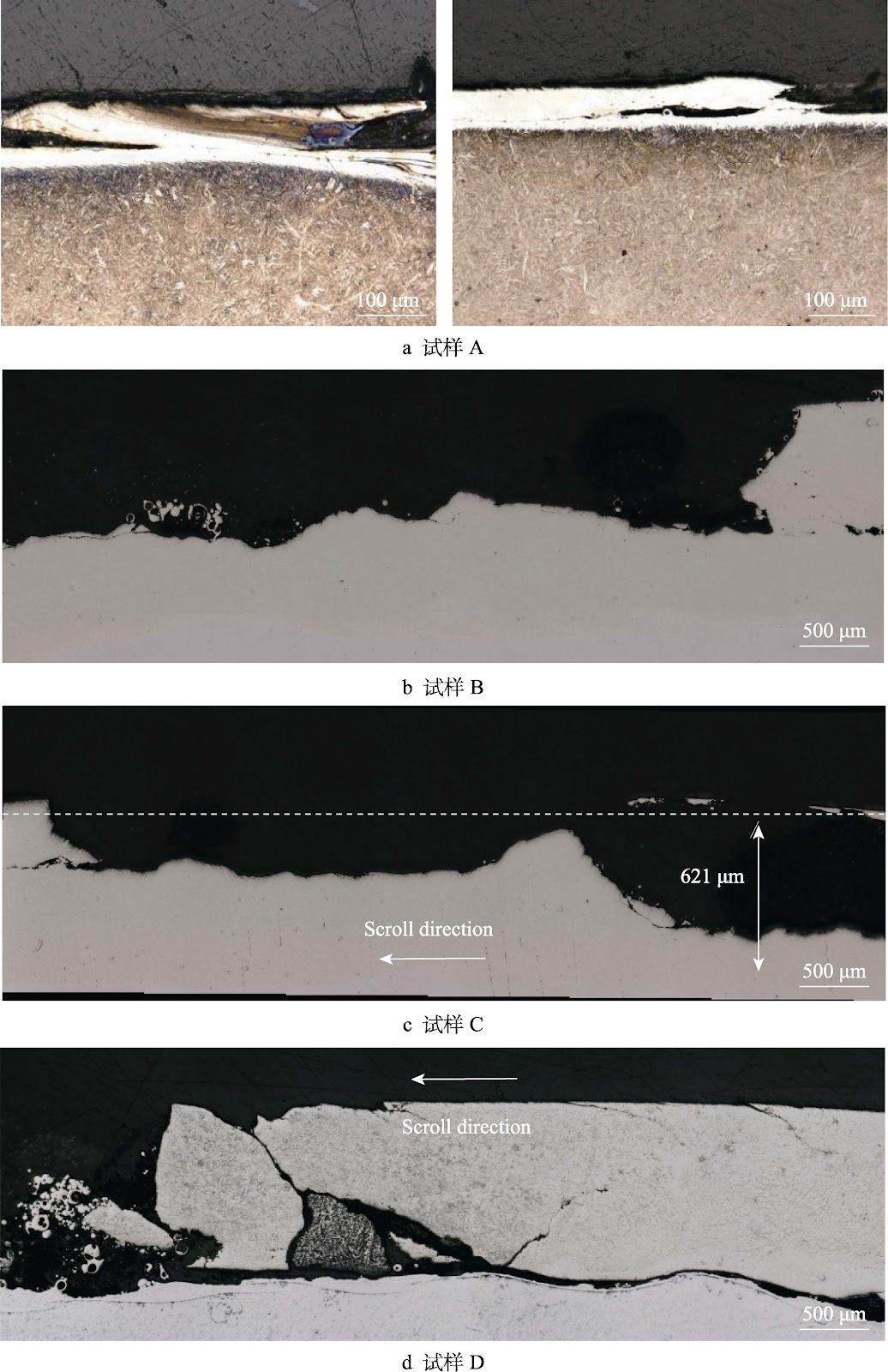
Scuffing constitutes a rapid, catastrophic failure mode in high-speed, heavy-duty gear transmissions, and enhancing scuffing load capacity remains a critical challenge for high-power-density systems. This study investigates the feasibility of laser cladding to improve scuffing resistance and repair scuffed tooth surfaces on 18CrNiMo7-6 gear steel. Three substrate conditions—tempered, carburized, and carburized with pre-induced scuffing damage—were coated with NiCr20-3%ZrO2-1%MoS2 (mass fraction) via a MobiMRO-2 laser cladding system with synchronous powder feeding. The cladded layer, approximately 1.2 mm thick, exhibited a dendritic, cellular, and irregular particulate microstructure with hardness of 690–730 HV0.1, comparable to the carburized case. Laser cladding induced significant heat-affected zone (HAZ) transformations: tempered steel formed lath martensite and lower bainite near the coating, with spheroidized structures in the lower HAZ; carburized steel developed coarse acicular martensite at the top, refined structures in the middle, and troostite at the bottom, with overall temper softening. Scuffing tests using a two-disc rolling contact rig under step-wise loading revealed that cladded tempered, cladded carburized, and repaired samples achieved 94.4%, 61.3%, and 50.7% increases in scuffing load capacity, respectively, relative to uncladded carburized baseline. This enhancement stems from increased hardness and the self-lubricating effect of the coating, which reduced interfacial friction coefficient and delayed critical failure. Failure analysis showed that the cladded layer altered crack initiation and propagation paths, significantly raising the critical failure load. The repaired samples, however, exhibited poor bonding at the original damage interface, leading to localized coating detachment. These findings confirm laser cladding as an effective method for enhancing gear scuffing resistance and repairing scuffed surfaces, providing experimental and theoretical support for surface strengthening and damage repair.
Numerical Simulation and Process Parameter Optimization of Laser Hardening for QT500-7 Ductile Cast Iron
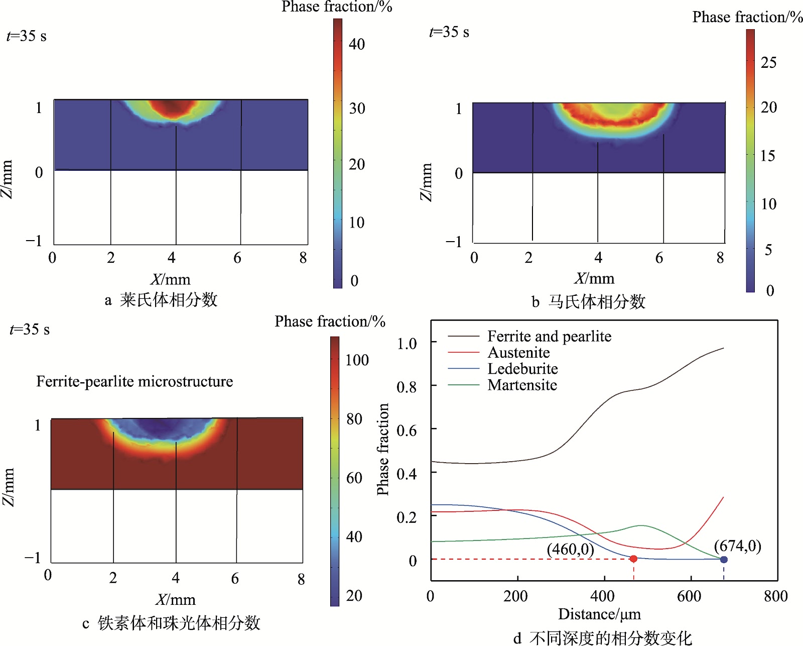
Laser surface hardening of QT500-7 ductile cast iron was investigated through a coupled finite element–machine learning–multi-objective optimization framework. A phase-transformation heat-transfer finite element model screened process windows for laser power (100–400 W), scanning speed (5–15 mm·s⁻¹), and overlap rate (60%–90%). A three-factor, three-level Box-Behnken design yielded hardened layer depth and fused layer depth as response variables. Four predictive architectures were benchmarked: Random Forest (RF), XGBoost, RF-XGBoost ensemble, and Bayesian-optimized RF-XGBoost (BO-RF-XGBoost). The BO-RF-XGBoost model achieved superior accuracy, with relative errors of 6.52% for hardened layer depth and 9.09% for fused layer depth. Multi-objective optimization compared Advantage Actor-Critic (A2C), Multi-Objective Particle Swarm Optimization (MOPSO), and Non-dominated Sorting Genetic Algorithm II (NSGA-II). A TOPSIS-entropy weight method ranked the Pareto front, identifying optimal parameters: laser power 230 W, scanning speed 14 mm·s⁻¹, overlap rate 75%. Experimental validation at these parameters produced a hardened layer depth of 230 μm and fused layer depth of 66 μm, with finite element model errors of 9.13% and 3.03%, respectively. Microhardness measurements showed the fused layer at 940 ± 40 HV0.5 and the hardened layer at 630 ± 30 HV0.5, both significantly exceeding the substrate hardness of 166 ± 15 HV0.5. The framework provides a reliable tool for parameter optimization in laser surface hardening of ductile cast iron.
Polishing of Glass-ceramics with Nano-silica Modified Magnetic Abrasives
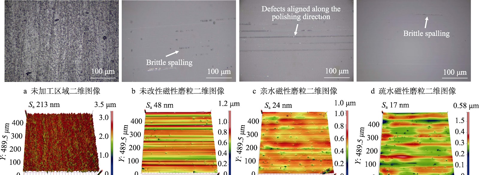
Glass-ceramics, multiphase composites combining amorphous and crystalline phases, exhibit disparate mechanical responses that induce subsurface damage and surface defects during conventional polishing. This study fabricates magnetic abrasive particles (MAPs) via a bonding process with three variants: unmodified, hydrophilic nano-silica (20 nm) modified, and hydrophobic nano-silica (20 nm) modified. Base composition comprises iron powder (75 μm) and CeO2 abrasives (15 μm) at a 12:3 mass ratio. Polishing tests on glass-ceramics using an N-S array tool reveal that hydrophobic modified MAPs achieve the lowest surface roughness (Sa = 17 nm) and highest material removal depth (2.5 μm), compared to hydrophilic (Sa = 24 nm) and unmodified (Sa = 48 nm) MAPs. Dynamic friction coefficients measured in situ are 0.31, 0.35, and 0.42 for hydrophobic, hydrophilic, and unmodified MAPs, respectively. Surface and subsurface damage analyses show hydrophobic MAPs minimize pits, micro-cracks, and brittle fractures, while hydrophilic MAPs exhibit brittle spalling and unmodified MAPs show point defects. Wear tests confirm that nano-silica addition enhances bond strength and extends abrasive lifespan. The hydrophobic modification promotes surface hydration and formation of a lubricating silicate gel layer, reducing mechanical plowing and friction, thereby enabling high-quality surface integrity. These findings demonstrate that nano-silica modification effectively tunes MAP hydrophobicity, offering a viable route for ultra-smooth, low-damage polishing of glass-ceramics.