Key Takeaways & Executive Findings
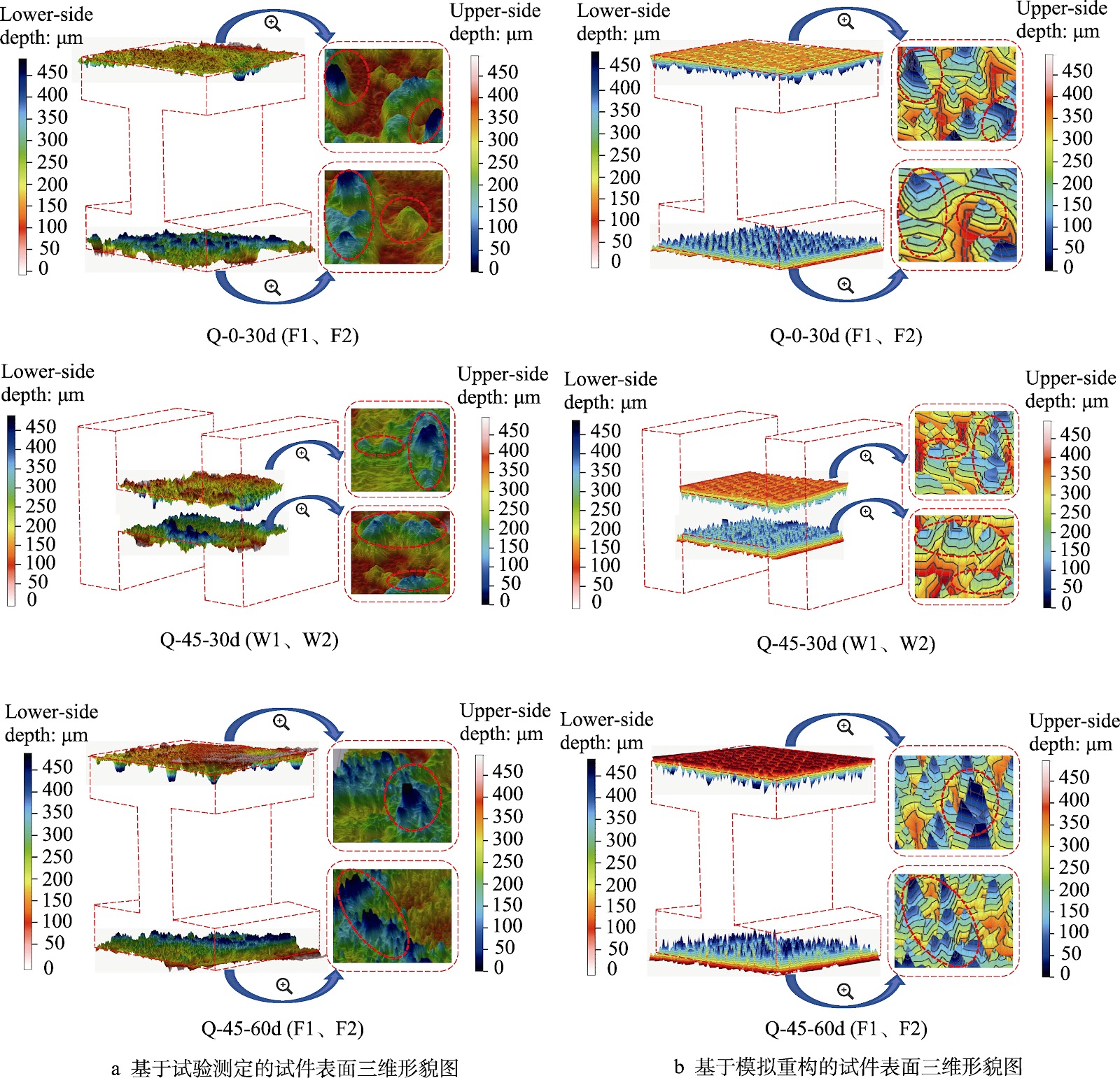
- •• • At 60 days of NSS exposure, the 45° inclined specimen's F1 surface exhibited average rust layer thickness and average pit depth 45.79% and 54.78% greater than the 0° horizontal specimen, respectively—quantifying the penalty for geometries that prevent protective electrolyte film formation and directly informing inspection intervals for inclined structural members. • • The 3D-CA corrosion model reproduced experimental pit morphology and depth with error below 5%, and simulated pit depth distributions followed a Weibull function, establishing a validated numerical tool for predicting spatially non-uniform corrosion damage without destructive testing. • • Spatial orientation dictates corrosion hierarchy: at 0° and 45°, upper flange > web > lower flange; at 90°, W1 > flanges > W2. This inversion at 90° means that inspection protocols derived from flat-plate data will systematically misallocate resources across H-section surfaces. • • The model's exclusion of coupled stress and external loading defines its current operational boundary; extrapolation to service conditions involving corrosion-fatigue interaction requires multi-scale extension, a limitation that must be accounted for in remaining-life assessments of load-bearing H-shaped steel components.
China Advanced Materials & Deep-Tech Radar
Get verified English translations, SEM micrographs & open-access PDF alerts from China's leading state key laboratories delivered to your inbox every Monday at 08:00 EST.
Abstract
H-shaped steel components are ubiquitous in steel structures, yet corrosion research has largely remained confined to two-dimensional flat plates, leaving the spatial-geometric effects on three-dimensional sections poorly quantified. This study addresses that gap through neutral salt spray (NSS) corrosion experiments on H-shaped steel specimens positioned at 0°, 45°, and 90° over corrosion cycles extending to 60 days, coupled with a three-dimensional cellular automata (3D-CA) model of the corrosion evolution. The spatial placement angle exerts a decisive influence on corrosion distribution. At 0° and 45°, the upper flange corrodes more severely than the web, while the lower flange remains least affected; the 45° specimen, however, exhibits accelerated attack because its inclined geometry prevents formation of a protective NaCl electrolyte film on the flanges. At 60 days, the 45° specimen's F1 surface shows average rust layer thickness and average pit depth exceeding those of the 0° specimen by 45.79% and 54.78%, respectively. At 90°, the W1 surface is most severely corroded, followed by the flanges, with W2 least affected. The 3D-CA model reproduces the time-dependent corrosion morphology, yielding pit depth distributions consistent with a Weibull function and agreeing with experimental pit morphology and depth within 5% error. The model is validated as a reliable predictor of spatially heterogeneous corrosion evolution in H-shaped steel, though it currently omits coupled stress and external loading effects.
1. Introduction
Structural steel corrosion research has historically relied on two-dimensional flat plate specimens, a simplification that fails to capture the spatially heterogeneous attack observed on real three-dimensional sections. H-shaped steel components, ubiquitous in modern steel construction, present a complex geometry in which flanges and web create distinct micro-environments for moisture retention, oxygen diffusion, and electrolyte accumulation. The resulting non-uniform corrosion patterns cannot be predicted from flat-plate data, yet systematic experimental and numerical studies on how spatial orientation governs corrosion evolution across individual H-section surfaces remain scarce. This knowledge gap leaves engineers without validated tools for allocating inspection resources or estimating remaining life in corrosion-prone H-shaped members.
This study confronts that bottleneck directly. Neutral salt spray experiments were conducted on H-shaped steel specimens positioned at 0°, 45°, and 90° over corrosion cycles up to 60 days, generating surface-resolved corrosion rate, rust layer thickness, and pit depth data. A three-dimensional cellular automata model was then constructed to simulate the dynamic corrosion process, incorporating the oxygen and chloride mechanisms operating under the electrolyte film. The experimental matrix specifically isolates spatial angle as the controlling variable, while the 3D-CA framework provides a predictive capability that flat-plate models cannot offer. Validation against measured pit morphology and depth distributions establishes the model's quantitative reliability and defines the conditions under which it can be applied.
Loading authentic research manuscript (Pages 1–5)...
LIU Zhe, GU Wenxu, BAN Huiyong, ZHOU Xuejun, WEI Ruida (2026). Test and Simulation Analysis on the Corrosion Evolution over Time of H-shaped Steel Components. Surface Technology (表面技术). https://doi.org/10.16490/j.cnki.issn.1001-3660.2026.12.004
Research & Educational Purpose Only: The translations, structured abstracts, analytical annotations, and data reports provided by SinoTechIntelare intended exclusively for academic research, internal corporate R&D, and educational benchmarking. They do not constitute formal engineering, chemical safety, legal, or professional advice.
Copyright & Intellectual Property Notice: Original copyright of the underlying source articles and experimental data remains with the respective authors, institutions, and original publishing journals. SinoTechIntel claims intellectual property only over its proprietary translations, analytical syntheses, and AEO structured enhancements in accordance with international fair use and academic citation principles.
Frequently Asked Questions
What is the dominant failure mechanism driving the accelerated corrosion observed at the 45° orientation, and how does it differ from the 0° and 90° cases?
At 45°, the inclined geometry prevents NaCl electrolyte from forming a stable protective film on the flanges, so the surface remains alternately wetted and dried rather than continuously covered. This intermittent wetting accelerates oxygen reduction and chloride attack, producing average rust layer thickness and pit depth on the F1 surface that exceed the 0° specimen by 45.79% and 54.78%, respectively, after 60 days. At 0°, the horizontal upper flange retains a more uniform electrolyte layer, moderating attack; at 90°, gravity drains the web faces differently, making W1 the most corroded surface and W2 the least.
The 3D-CA model reports pit depth error within 5%—what is the experimental baseline for that figure, and does it hold across all three spatial orientations?
The 5% error bound is established by comparing simulated pit morphology and depth distributions against measured NSS corrosion data after the full 60-day cycle. Simulated pit depths follow a Weibull distribution, matching the spatial non-uniformity and randomness seen in the experiments. The validation covers the 0°, 45°, and 90° specimens, with the closest agreement on surfaces where the electrolyte film behavior is well captured by the oxygen and chloride transport rules. Surfaces subject to more complex film dynamics, such as the 45° flanges, represent the upper end of the error range.
What are the scalability bottlenecks in applying this 3D-CA model to full-scale H-section members or large structural assemblies?
The current model operates at the coupon scale and does not incorporate coupled stress states or external loading, which are unavoidable in service. Extending it to full-scale members requires multi-scale coupling from microstructural pit initiation to macroscopic property degradation, plus calibration against field exposure data rather than accelerated NSS results. Computational cost scales with the number of cells needed to resolve pit geometry across meter-scale components, so mesh coarsening strategies and parallelization will be necessary before plant-level or bridge-level deployment.
How should inspection and maintenance protocols for H-shaped steel structures be revised based on the orientation-dependent corrosion hierarchy reported here?
The data show that a single corrosion allowance derived from flat-plate tests will misallocate inspection effort. For horizontal or near-horizontal members, the upper flange and web demand priority; for inclined members near 45°, the flanges—especially F1—require the shortest inspection interval because of the 45.79% and 54.78% penalties in rust thickness and pit depth relative to 0°. For vertical members at 90°, W1 becomes the critical surface, with flanges secondary and W2 least affected. Inspection schedules should therefore be indexed to both member orientation and surface position rather than treated as uniform.
What is the cost or performance trade-off between the 3D-CA simulation approach and conventional empirical corrosion models for engineering practice?
Conventional empirical models are inexpensive but cannot resolve surface-to-surface variation within a single H-section, which the present experiments show can exceed 50% in pit depth between orientations. The 3D-CA model requires computational resources and calibration data but delivers spatially resolved pit depth distributions with under 5% error, enabling targeted inspection and more accurate remaining-life estimates. The trade-off is justified where corrosion-driven failure carries high consequence or where inspection access is costly; for low-risk, uniformly exposed members, empirical allowances may remain sufficient.
Related Chinese Research & Cross-Citations
Research Progress and Prospects of Corrosion-resistant High-entropy Alloy Coatings
Marine environments impose combined electrochemical, microbiological, and cavitation erosion degradation on metallic infrastructure, shortening service intervals and inflating maintenance expenditure. High-entropy alloy (HEA) coatings mitigate these failure modes through simple solid-solution or amorphous microstructures that suppress galvanic coupling and promote dense passive film formation. This review systematically examines corrosion-resistant HEA coatings from single-factor to multi-factor coupling perspectives, covering classification and compositional design, fabrication routes, and corrosion behavior under complex marine conditions. Key coating systems include FeCoCrNiMn, AlCoCrFeNi, FeCrNiCoAl, and (FeCoCrNi)75B15Si10 amorphous alloys deposited by atmospheric plasma spraying, high-velocity oxy-fuel spraying, and wire arc spraying. Elemental additions of Cr, Al, and Mo enhance passivation; B and Si promote amorphous phase formation. The review identifies core engineering bottlenecks: compositional design, process optimization, and service performance validation. A multi-scale simulation, process-structure optimization, and in-situ characterization framework is proposed to accelerate coating deployment. These findings provide theoretical and technical guidance for next-generation corrosion-resistant coatings in marine equipment.
Effect of Sodium Hypochlorite Concentration and Medium Temperature on Corrosion of 45# Steel in Artificial Seawater and Simulated Concrete Pore Solution
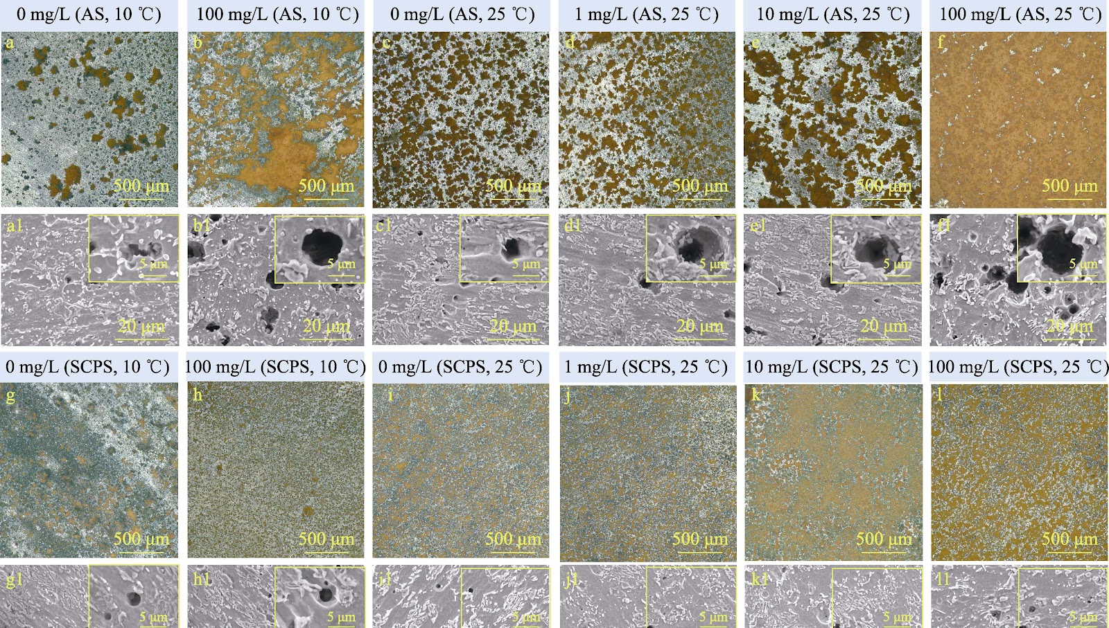
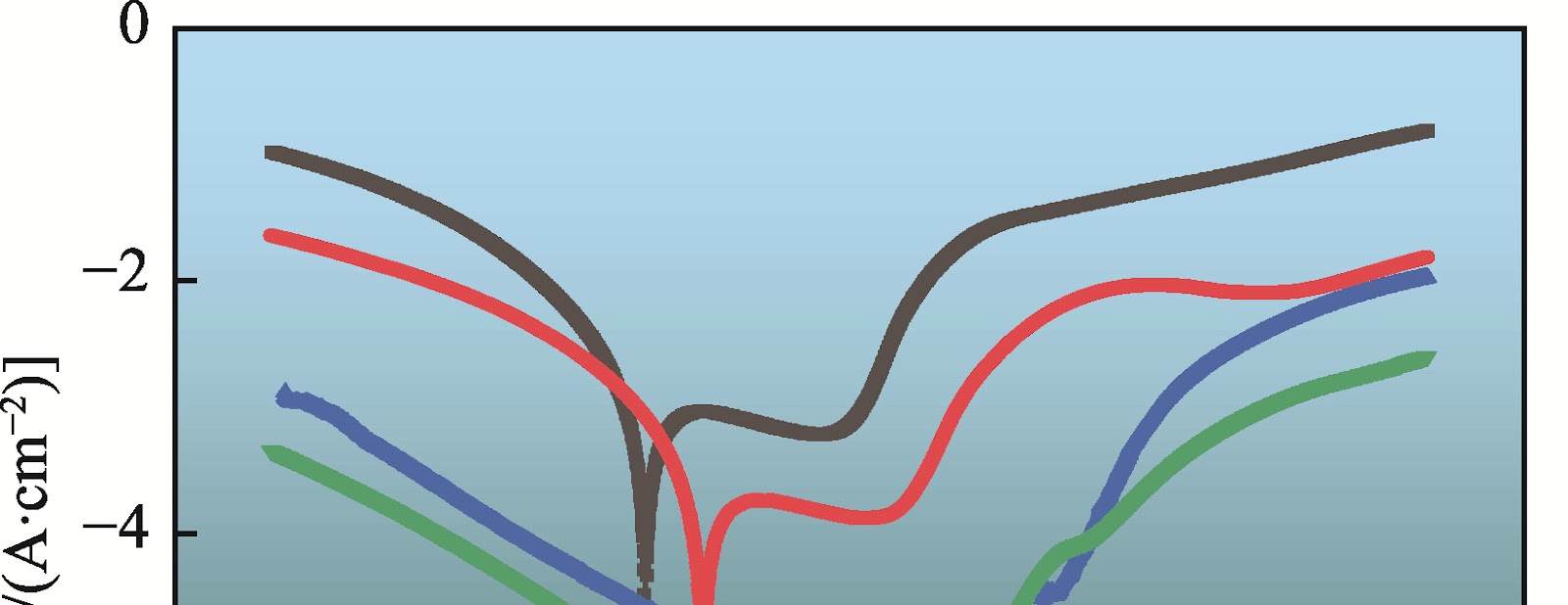
Seawater discharged during LNG regasification carries residual chlorine, predominantly sodium hypochlorite (NaClO), and low temperature, posing a dual corrosion threat to carbon steel components and adjacent reinforced concrete. This study systematically evaluates the corrosion behavior of 45# steel in artificial seawater (AS) and simulated concrete pore solution (SCPS, pH≈10) under NaClO concentrations of 0, 1, 10, and 100 mg/L at 10 °C and 25 °C. Electrochemical impedance spectroscopy, potentiodynamic polarization, weight-loss measurements, and localized corrosion-depth analysis were combined with SEM, EDS, XPS, and XRD to resolve corrosion kinetics, morphology, and product composition. In AS at 25 °C, increasing NaClO from 0 to 100 mg/L decreased charge transfer and film resistance (Rct + Rf) from 2266 to 1207 Ω·cm² and increased corrosion current density (Jcorr) from 11.48 to 18.29 μA/cm². Weight-loss rates remained 0.108 mm/a at 0 and 1 mg/L NaClO, rose slightly to 0.123 mm/a at 10 mg/L (+13%), and sharply to 0.202 mm/a at 100 mg/L (+87%). Corrosion morphology shifted from localized to uniform, with reduced pit depth. In SCPS at 25 °C, the alkaline environment suppressed NaClO-induced acceleration: Rct + Rf decreased from 2922 to 2266 Ω·cm², and weight-loss rates increased only 8% (0.0937 mm/a) at 10 mg/L and 25% (0.108 mm/a) at 100 mg/L relative to the 0.0865 mm/a control. However, 100 mg/L NaClO in SCPS significantly deepened localized pits. At 10 °C, both media exhibited reduced corrosion current density, thinner product layers, and shallower pits. Under standard discharge conditions (residual chlorine ≤0.2 mg/L), the additional corrosion risk from cold discharge water is negligible.
Corrosion Inhibition Mechanism of Typical Inorganic Inhibitors on Stainless Steel in a Simulated Electrolytic Seawater Environment
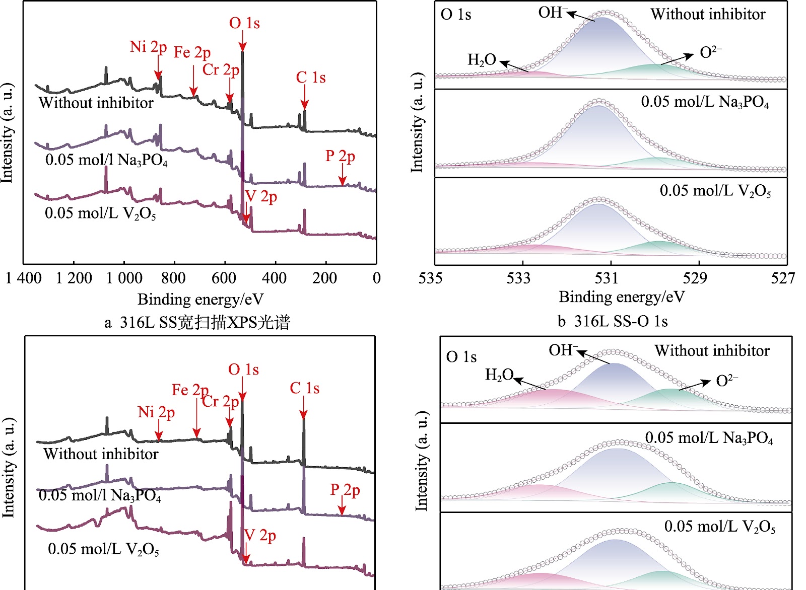
Alkaline seawater electrolysis for hydrogen production imposes severe corrosion on structural stainless steels, particularly in high-temperature, highly alkaline, chloride-rich electrolytes. This study evaluates four inorganic inhibitors—sodium molybdate (Na2MoO4), sodium tungstate (Na2WO4), sodium phosphate (Na3PO4), and vanadium pentoxide (V2O5)—for 316L austenitic stainless steel (316L SS) and 2205 duplex stainless steel (2205 DSS) in a simulated electrolytic seawater environment (6.0 mol/L NaOH, 2.0 mol/L NaCl, 90 °C). Potentiodynamic polarization, electrochemical impedance spectroscopy (EIS), and 14-day immersion tests quantified inhibition efficiency (IE). Surface morphology and film chemistry were characterized by SEM, optical profilometry (OP), and XPS. V2O5 exhibited the highest IE, reaching 79.90% for 316L SS and 89.58% for 2205 DSS at 0.05 mol/L, followed by Na3PO4 (83.33% for 2205 DSS). Na2MoO4 and Na2WO4 were least effective. EIS fitting revealed that V2O5 markedly increased film resistance (Rf) and charge-transfer resistance (Rct) (e.g., Rct = 29,770 Ω·cm², Rf = 923.50 Ω·cm² for 316L SS), indicating suppressed interfacial charge transfer. XPS confirmed the incorporation of V4+/V5+ and PO4³− species into the surface film, forming a dense, barrier-type vanadium/phosphate composite layer that mitigates corrosion. These findings establish V2O5 and Na3PO4 as promising inhibitors for stainless steel in harsh alkaline electrolytic seawater systems.
Influence of Temperature on Diffusion Behavior and Infiltration Layer Structure of Sherardizing on Structural Steel
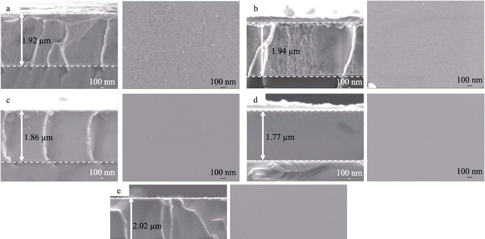
Powder sherardizing on Q235 structural steel was conducted in a 70wt.% Zn–0.8wt.% NH4Cl–29.2wt.% α-Al2O3 activated pack at 340–400 °C for 2–10 h to establish the temperature-dependent growth kinetics, phase evolution, and corrosion performance of Zn–Fe intermetallic layers. Cross-sectional SEM/EDS and XRD show that all layers consist of δ and Γ phases, with Γ concentrated near the substrate; excessive Γ at 340 °C initiates interfacial cracking. Layer thickness increases monotonically with temperature and time, rising from 10.80 μm at 340 °C to 43.90 μm at 400 °C after 6 h, and from 12.10 μm at 2 h to 81.60 μm at 10 h at 380 °C. The Zn/Fe ratio and δ-phase fraction increase with temperature, yielding denser layers and improved corrosion resistance; at 380–400 °C, corrosion current densities fall to 1.16×10⁻⁶–9.78×10⁻⁷ A/cm². The diffusion coefficient at 380 °C is 2.341×10⁻¹³ m²/s. Prolonged holding beyond 6 h produces through-thickness cracks. DSC and microstructural evidence support a three-stage growth mechanism: formation of active Zn atoms via ZnCl2 decomposition, bidirectional Zn/Fe interdiffusion along substrate defects, and continuous inward advancement of the Zn–Fe intermetallic front. The optimal processing window is 380 °C for 6 h, yielding a ~36.1 μm crack-free layer with 84.1% δ phase and superior corrosion resistance.
Research Progress and Problem Analysis on Corrosion Prediction of Supercritical CO2 Transport Pipelines
Pipeline transport is the core of large-scale CO2 delivery in CCUS projects, and supercritical pipeline transport is the most economical and feasible method. However, inherent multicomponent impurities and complex aqueous phase precipitation make corrosion control difficult and costly. This review assesses corrosion mechanisms and prediction technologies for supercritical CO2 transport pipelines, focusing on numerical analysis, supporting experiments, and field application within comprehensive mechanistic models. Current understanding has clarified the effects of individual impurities (H2O, H2S, O2, SO2, N2O, N2, H2, CH4) and operating parameters, but synergistic mechanisms of mixed gases remain unresolved, lacking systematic quantitative description. Existing prediction models are limited in applicability to corrosion conditions, morphological matching, and comprehensiveness of factors. Experimental methods suffer from insufficient reliability, particularly in precise metering and replenishment of corrosive media under low water content and multicomponent impurity synergy. Field application faces challenges in rational model use and accurate extraction of field data. Future directions include: deepening research on synergistic effects of impurity gases and quantifying them via theoretical analysis to establish mapping between impurity concentration and corrosion rate; accelerating development of aqueous phase precipitation and distribution models, multicomponent impurity water chemistry models, thermodynamic and kinetic models for multicomponent reactions, and competitive formation/growth models for multiple product films; strengthening experimental techniques for precise metering and replenishment under low water and multicomponent synergy; and improving field application by understanding model parameter physical meanings, applicability boundaries, and ensuring reasonable input parameters and accurate field data extraction.
Research on Wear Resistance and Wear Mechanism of NM500 Steel in a Wide Temperature Range
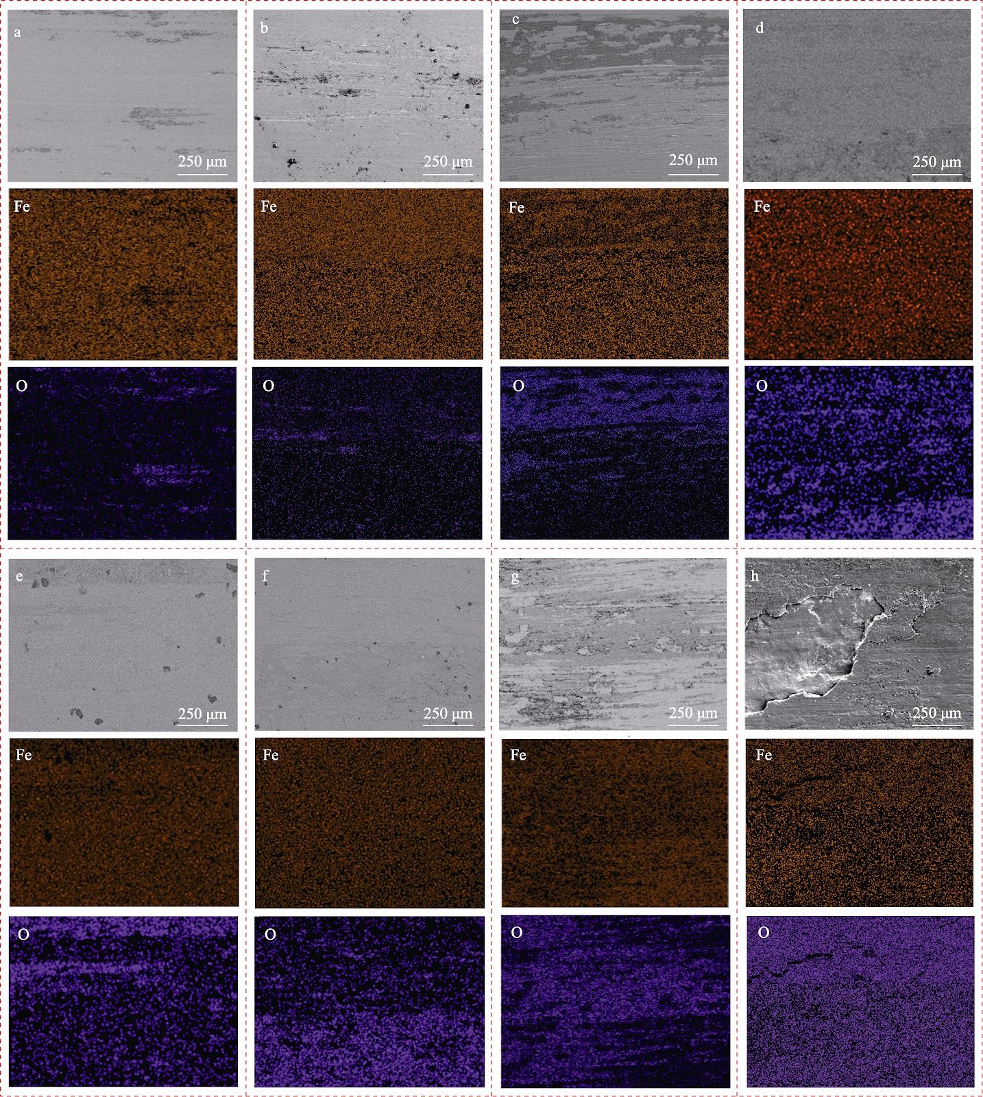
The tribological behavior of NM500 wear-resistant steel was systematically evaluated across a wide temperature range from −50 to 600 °C to elucidate the influence of temperature on wear resistance and to provide a theoretical basis for service life extension. Friction and wear tests were conducted using a high-temperature tribometer under a normal load of 150 N, rotational speed of 354 r/min, wear track diameter of 15 mm, and test duration of 60 minutes. The microstructure was characterized by SEM and EBSD, while worn surfaces were analyzed using XRD, SEM, and 3D laser confocal microscopy. NM500 steel exhibits a fine lath martensitic structure with a grain size of 7.08 μm, conferring high hardness and superior wear resistance. At cryogenic temperatures (−50, −25, 0 °C), the wear mechanism is predominantly abrasive wear, with a wear rate of only 1.29×10⁻⁶ mm3/(N·m). As temperature increases, oxide formation on the worn surface intensifies, friction coefficient decreases to a minimum of 0.3 (50% lower than at low temperature), and wear rate increases significantly: 18×10−6, 22.7×10⁻⁶, 46.7×10⁻⁶, and 128×10−6 mm3/(N·m) at 100, 200, 300, and 600 °C, respectively. The dominant wear mechanism transitions from abrasive wear at low temperatures to oxidative wear with adhesive wear at elevated temperatures. At 600 °C, thermal softening, reduced texture strength, and oxide film delamination exacerbate material loss, shifting the mechanism to oxidative wear as the primary mode with adhesive wear as secondary.