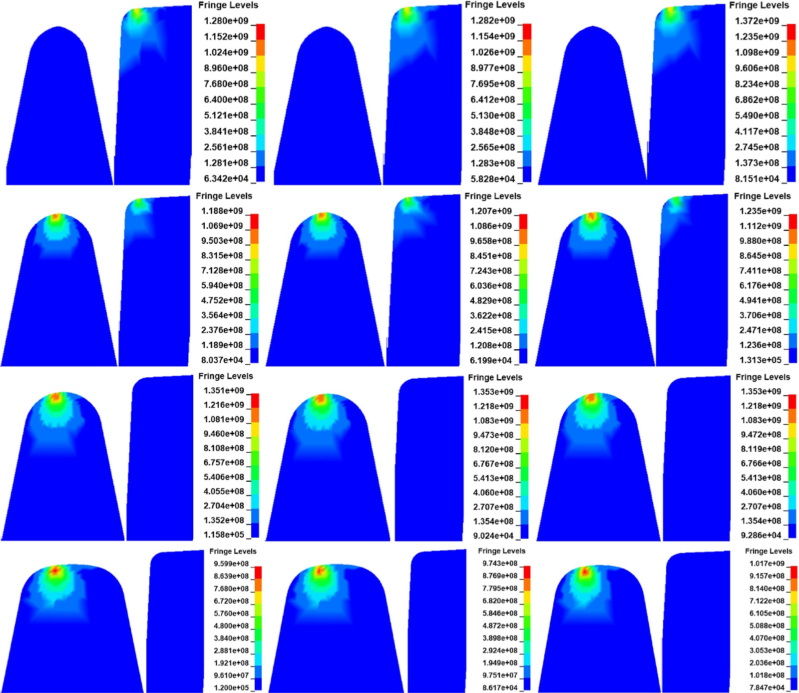
Key Takeaways & Executive Findings
- •• • The 30 mm top width cross-section of the nose rail is identified as the critical fatigue-prone zone, with crack initiation occurring on the rail surface. This localization enables targeted inspection and maintenance protocols, potentially reducing unplanned track failures by focusing non-destructive testing on this specific geometric region. • • Crack initiation angles relative to the lateral direction range from 70° to 95°, while vertical orientation angles remain unpredictable. This angular constraint provides a quantitative basis for designing crack-arresting features or surface treatments, as the predominant lateral orientation governs the stress intensity factor driving crack propagation. • • Increasing fastener vertical stiffness slightly amplifies wheel–rail impact response, but the effect is marginal. The calculated RCF crack initiation life is approximately 24,000 cycles under three different stiffness conditions, indicating that fastener stiffness optimization alone cannot substantially extend frog service life, necessitating alternative mitigation strategies. • • Higher vehicle speeds result in shorter fatigue life, establishing a direct operational trade-off between subway speed increases and turnout component durability. This speed-dependent degradation rate must be incorporated into maintenance scheduling and speed restriction policies to prevent accelerated crack initiation in fixed frogs.
China Advanced Materials & Deep-Tech Radar
Get verified English translations, SEM micrographs & open-access PDF alerts from China's leading state key laboratories delivered to your inbox every Monday at 08:00 EST.
Abstract
The escalating traffic density and operational speeds of subway systems have intensified fatigue damage in turnout rails, particularly within the hazardous space of fixed frogs where wheel–rail dynamic interaction is exacerbated. This study addresses the rolling contact fatigue (RCF) crack initiation behavior of a No. 9 turnout fixed frog, a configuration widely deployed in subway networks. A three-dimensional explicit transient rolling contact finite element model was developed to simulate wheel–rail interaction under varying vehicle speeds and fastener vertical stiffness conditions. The analysis focused on crack initiation locations, angles, and fatigue life. Results demonstrate that the 30 mm top width cross-section of the nose rail is the most susceptible to fatigue cracking, with cracks initiating on the rail surface. The angle between the crack initiation surface and the lateral direction ranges from 70° to 95°, while the angle relative to the vertical direction remains difficult to predict. Higher vehicle speeds significantly reduce fatigue life, whereas fastener vertical stiffness exerts a minor influence. The calculated RCF crack initiation life is approximately 24,000 cycles across three stiffness conditions. Simulation outcomes align with field survey findings, validating the model's fidelity. The established methodology provides theoretical support for optimizing fixed frog structures and predicting fatigue life in subway turnouts.
1. Introduction
Subway systems globally face a persistent engineering bottleneck: fixed frogs in turnouts, despite their structural integrity and low maintenance demands, generate severe wheel–rail impact forces due to their discontinuous running surfaces. These impact forces, exacerbated by rising traffic density and operational speeds, drive rolling contact fatigue (RCF) crack initiation on nose rails and wing rails, leading to spalling, fracture, and potential derailment. Existing multi-rigid-body dynamics models, while useful for vehicle–turnout interaction analysis, fail to capture the transient contact mechanics and material-level stress states necessary to predict crack initiation life with sufficient accuracy. Field surveys consistently report fatigue damage at specific frog locations, yet a validated predictive framework linking operational parameters to crack initiation thresholds has been absent.
This study addresses that gap by establishing a three-dimensional explicit transient rolling contact finite element model of a No. 9 turnout fixed frog, incorporating realistic wheel–rail contact geometry and material behavior. The model simulates dynamic rolling contact under varying vehicle speeds and fastener vertical stiffness conditions, enabling direct calculation of crack initiation locations, angles, and fatigue life. By correlating simulation outputs with field-observed damage patterns, the investigation provides a validated methodology for predicting RCF crack initiation in fixed frogs. The findings deliver quantitative thresholds—such as the 30 mm top width cross-section as the critical zone and a fatigue life of approximately 24,000 cycles—that can be directly integrated into turnout design optimization and maintenance planning, thereby reducing the risk of sudden track failure in subway networks.
Loading authentic research manuscript (Pages 1–5)...
Zheng Zhaoguang, Dong Zhiguo, Hu Jiayi, Xu Jingmang, Wang Kai, Wang Ping (2026). Investigation on the Rolling Contact Fatigue Cracks Initiation of Subway Fixed Frogs Based on Transient Dynamics. Railway Engineering Science (铁道工程科学). https://doi.org/10.1007/s40534-025-00388-2
Research & Educational Purpose Only: The translations, structured abstracts, analytical annotations, and data reports provided by SinoTechIntelare intended exclusively for academic research, internal corporate R&D, and educational benchmarking. They do not constitute formal engineering, chemical safety, legal, or professional advice.
Copyright & Intellectual Property Notice: Original copyright of the underlying source articles and experimental data remains with the respective authors, institutions, and original publishing journals. SinoTechIntel claims intellectual property only over its proprietary translations, analytical syntheses, and AEO structured enhancements in accordance with international fair use and academic citation principles.
Frequently Asked Questions
What is the primary failure mechanism driving rolling contact fatigue crack initiation in subway fixed frogs, and how does the 30 mm top width cross-section of the nose rail become the critical zone?
The failure mechanism is cyclic wheel–rail impact loading concentrated at the geometric discontinuity of the frog, where the wheel transitions from the wing rail to the nose rail. This transition generates elevated contact stresses and plastic deformation. The 30 mm top width cross-section of the nose rail experiences the most severe stress concentration because it represents the initial contact point during wheel transfer, resulting in surface-initiated cracks. Field surveys confirm this location as the predominant damage site, validating the simulation's predictive accuracy.
How does vehicle speed quantitatively affect the rolling contact fatigue crack initiation life of fixed frogs, and what are the implications for subway operational speed limits?
Higher vehicle speeds significantly reduce fatigue life. The study calculates a crack initiation life of approximately 24,000 cycles under baseline conditions, but this value decreases as speed increases due to amplified impact forces and stress intensities. For subway operators, this establishes a direct trade-off: increasing speed to boost throughput accelerates fatigue damage, necessitating more frequent inspection and potentially shorter replacement intervals for fixed frogs. Speed restrictions may be required in high-traffic turnouts to maintain safety margins.
What is the influence of fastener vertical stiffness on crack initiation life, and can stiffness optimization alone mitigate fatigue damage?
Increasing fastener vertical stiffness slightly enhances the wheel–rail impact response, but the effect on crack initiation life is marginal. The calculated life remains approximately 24,000 cycles across three different stiffness conditions. The crack initiation angle relative to the lateral direction varies minimally, typically between 70° and 95°. Therefore, fastener stiffness optimization alone cannot substantially extend frog service life; complementary strategies such as material hardening, profile optimization, or surface treatments are necessary.
How do the predicted crack initiation angles compare with field observations, and what is the practical significance of the 70°–95° lateral angle range?
The predicted crack initiation angles relative to the lateral direction range from 70° to 95°, which aligns well with field study results. The angle with the vertical direction remains challenging to predict. This lateral orientation dominance indicates that the principal stress driving crack initiation is predominantly lateral, providing a quantitative basis for designing crack-arresting features or applying surface treatments oriented to resist lateral crack propagation. Maintenance inspections should prioritize detecting cracks within this angular range.
What are the scalability and implementation bottlenecks for applying this transient dynamics model to optimize fixed frog structures across diverse subway networks?
The primary bottleneck is computational cost: explicit transient finite element simulations of rolling contact require high-performance computing resources and detailed material models. Scalability depends on calibrating the model for different turnout geometries (e.g., No. 9 vs. other numbers), axle loads, and wheel profiles. However, the validated correlation with field data provides a template that can be adapted. Implementation requires integrating the model into design workflows, where parametric studies can identify optimal nose rail profiles and fastener configurations, reducing reliance on costly field trials.
Related Chinese Research & Cross-Citations
Punching test for mechanical characterization of asphalt railway sub-ballast
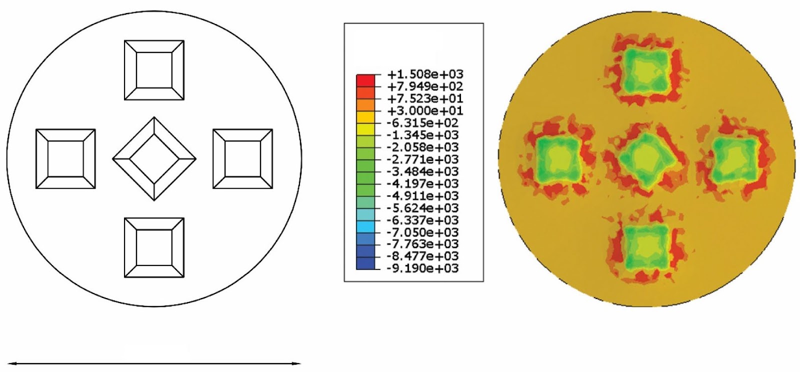
The adoption of asphalt sub-ballast layers in high-speed and high-capacity railway lines has gained traction across Europe and the United States, driven by structural, functional, and economic advantages. However, current mechanical characterization methods, inherited from road paving practice, fail to capture railway-specific interactions, particularly the ballast/sub-ballast interface and the granular behavior of the overlying unbound layer. This study introduces a novel punching test employing an adaptive indentation plate (AIP) to replicate the contact between ballast particles and the sub-ballast. Cylindrical asphalt specimens (150 mm diameter) were subjected to vertical point loads via the AIP at temperatures of 5, 20, and 35 °C and deformation rates of 5.08, 25.4, and 50.8 mm/min. Two asphalt mixes compliant with Italian sub-ballast standards—one with conventional B50/70 binder (SSB) and one with polymer-modified PmB 45/80-65 (HSB)—were tested to validate the procedure. Force–displacement curves revealed three interaction phases, and key parameters such as peak force (Fmax), displacement at peak force (uy,*), force at 1.5 mm deflection (Fu,1.5), and secant slope (m) between 1.25 and 1.75 mm were extracted. Results demonstrate that the punching test effectively evaluates resistance to plastic deformation and indentation behavior, offering insights beyond existing specifications. The lowest deformation rate (5.08 mm/min) best captures viscoelastic properties. This methodology provides a valuable tool for assessing bituminous sub-ballast performance under simulated railway interface conditions.
Dynamic Models and Analysis of Key Factors Influencing Stick–Slip Vibration in Disc Brake Systems
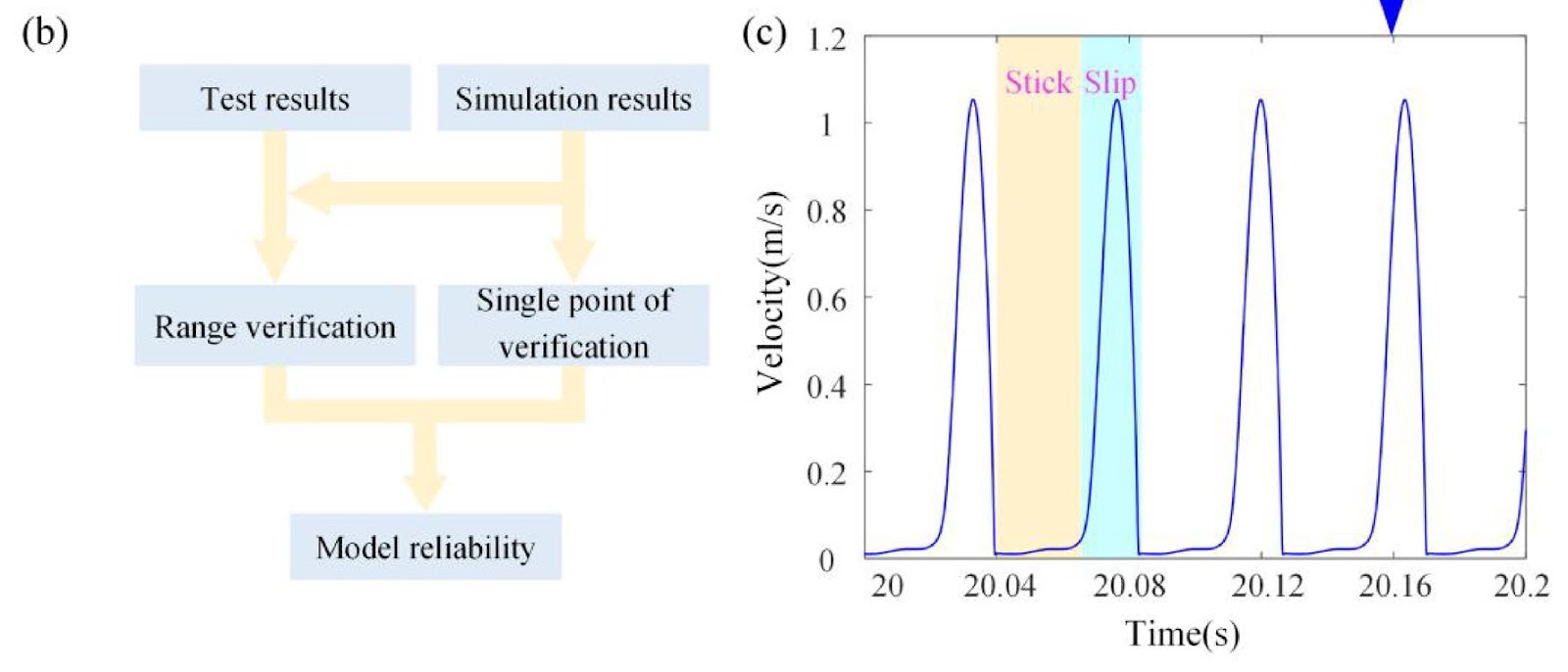
Stick–slip vibration in disc brake systems at low speeds arises from the interaction of multiple factors, posing persistent challenges for high-speed train safety and passenger comfort. This study establishes three- and four-degree-of-freedom (DOF) dynamic models that incorporate wheel–rail adhesion and nonlinear friction, validated through line testing. System stability, stick–slip bifurcation characteristics, and key influencing factors are analyzed via numerical simulation. Results demonstrate that the four-DOF model, by accounting for normal motion, avoids the over-evaluation of system stability inherent in the three-DOF model. In the three-DOF model, tangential stiffness is the primary factor inducing chaotic stick–slip vibration. In the four-DOF model, tangential stiffness predominantly affects vibration amplitude, while normal stiffness governs the onset of chaos. Damping exhibits minimal influence on chaotic stick–slip occurrence. Optimal parameter ranges are identified: brake disc rotational inertia of 5–9 kg·m² and 11–22 kg·m², and friction pad mass of 7–17 kg, which effectively mitigate chaotic stick–slip vibration. These findings provide quantitative guidelines for brake system design, enhancing operational reliability and reducing wear-related failures in high-speed rail applications.

Acoustic characteristic optimal design for railway steel–concrete composite bridge based on the RBFNN-NSGA-II algorithm
Structure-borne noise from railway steel–concrete composite (SCC) bridges presents a persistent challenge due to high sound pressure levels across both low and high frequency ranges. This study establishes a hybrid finite element–statistical energy analysis (FE-SEA) numerical model to predict acoustic radiation from an SCC bridge. Field measurements validate the model with discrepancies of only 0.4 dB and 1.1 dB in overall sound pressure levels. Using uniform design sampling, a high-accuracy radial basis function neural network (RBFNN) surrogate is trained to map cross-sectional parameters to acoustic and cost objectives. The non-dominated sorting genetic algorithm (NSGA-II) then performs multi-objective constrained optimization, generating a Pareto frontier for sound power level (SWL) and material cost. The technique for order preference by similarity to an ideal solution (TOPSIS) selects the optimal parameter combination, achieving a 5 dB reduction in SWL and a 23.9% decrease in material cost. These results demonstrate that strategic cross-sectional adjustments can simultaneously mitigate noise and reduce expenditure, offering a practical framework for acoustic optimization in railway bridge design.
A modular simulation tool for fixed block and moving block railway signalling systems
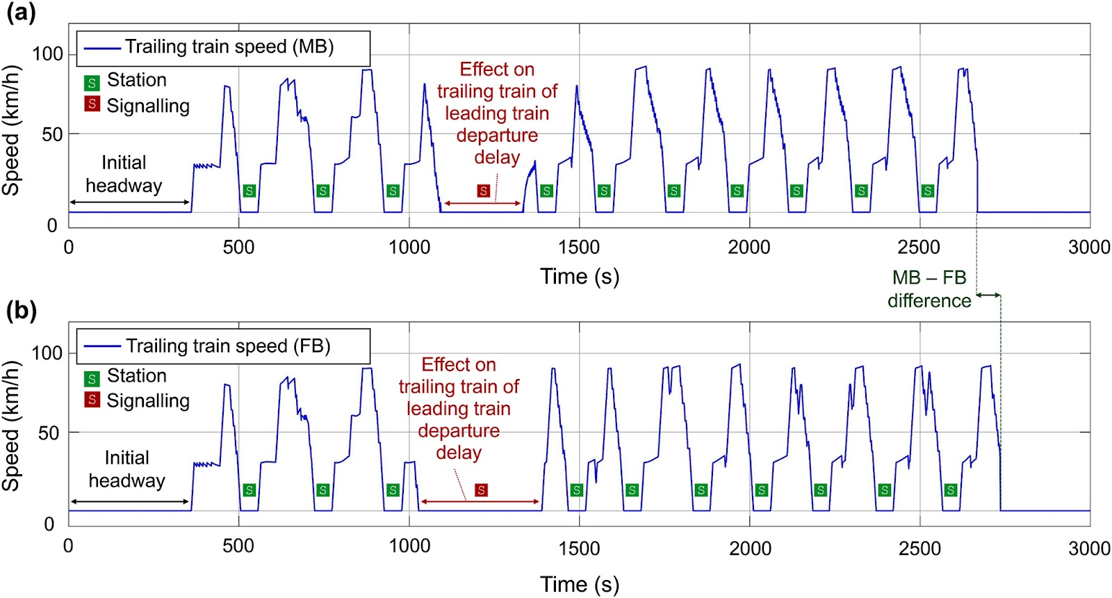
This paper presents a time-based modular simulation tool implemented in MATLAB® and Simulink® for evaluating fixed block (FB) and moving block (MB) railway signalling systems. The simulator integrates the Radio Block Centre (RBC), On-Board Unit (OBU), vehicle longitudinal dynamics, and a driver behavioural model to replicate realistic train operations. Two case studies are conducted on a main railway line with twelve stations, involving a leading and a trailing train with identical mechanical characteristics. An unexpected departure delay of the leading train at the fifth station reduces the headway, forcing the signalling system to intervene. Simulation A employs identical driver parameters for both trains, while simulation B assigns an aggressive and less responsive driver to the trailing train, resulting in a more pronounced signalling action. Results indicate that MB signalling reduces the trailing train's travel time by 70 s (2.5% of total time) compared to FB, albeit with a more jagged speed profile due to frequent activations. The authors caution that these findings are limited to the two case studies and that a comprehensive parametric investigation is necessary for generalised conclusions. The tool aims to reduce on-site testing of railway signalling systems by providing a flexible platform for scenario analysis.

Performance-based comprehensive functional damage probability assessment framework for high-speed railway bridge under earthquake
Current seismic damage assessments for high-speed railway (HSR) bridges primarily focus on overall structural safety, lacking evaluations from multiple performance perspectives, which affects post-earthquake traffic decision-making. This study proposes a performance-based comprehensive functional damage probability assessment framework for high-speed railway simply supported bridges (HSRSSBs) under earthquakes. The framework categorizes bridge functions into three levels: post-earthquake traffic function (PTF), structural bearing function (SBF), and collapse resistance function (CRF), corresponding to operational, structural safety, and structural integrity requirements, respectively. By analyzing damage states of key bridge components during earthquakes, functional damage probability assessment indicators and classification thresholds are established according to various performance requirements. Damage probability calculations are conducted using the probability density evolution method and vulnerability method. Based on the relationship between damage probabilities at different functional levels, a comprehensive damage probability assessment framework considering the three-level performance requirements of HSRSSBs is developed, and the influence of varying pier heights on the functional damage probability relationship is examined. Results indicate that current HSRSSB designs meet all performance requirements under frequent earthquakes. Under design-level earthquake conditions, the SBF remains in a slight damage state, while the PTF exhibits varying degrees of damage, which worsens as pier height increases. The pier structure satisfies seismic demands even under rare earthquake conditions.
Numerical study on aerodynamic noise reduction of high-speed pantograph using base-frame fairing
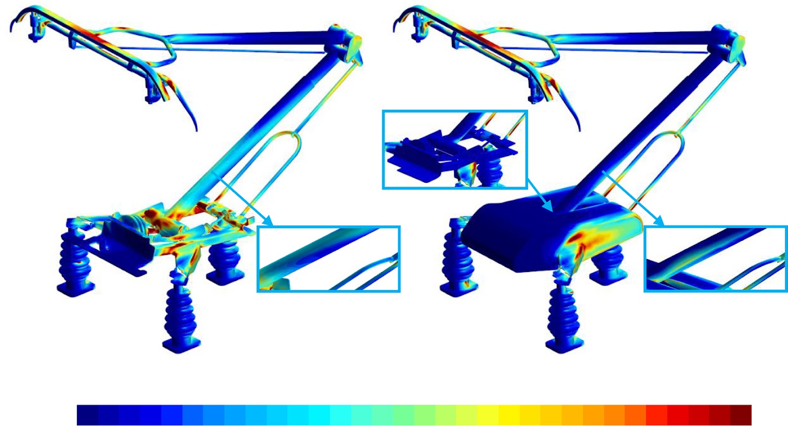
A hybrid improved delayed detached eddy simulation (IDDES) and Ffowcs Williams–Hawkings (FW-H) acoustic analogy framework is applied to quantify the aerodynamic noise mitigation potential of base-frame fairings on a high-speed pantograph operating at 400 km/h. Two fairing configurations—solid and perforated—are evaluated without altering the pantograph's bottom structural architecture. The solid fairing effectively shields the base-frame and suppresses flow separation at the pantograph bottom, yet it introduces flow deflection and acceleration that elevate noise generation in the top and mid regions. A previously underreported self-noise mechanism is identified: wake impingement from unshielded insulator beams onto the fairing side surface generates high-amplitude pressure fluctuations, compromising net noise reduction. Smoothing the insulator beams mitigates this effect. The perforated fairing outperforms the solid variant by providing an additional airflow pathway through small holes, which reduces lateral and upward flow acceleration and promotes wake vortex suppression. Airflow ejected from leeward holes pushes vortex structures downstream, forming a stable, low-fluctuation region near the fairing tail and significantly reducing dipole source strength. Aerodynamic drag is reduced by 21.8% with fairing installation, though lift fluctuation of the strip is exacerbated by flow deflection. These findings establish perforated base-frame fairings as a superior noise-control strategy for high-speed pantograph systems.